
Building a house is a very complex and systematized process. For a house to be built from the ground up, the Architect must set up a system on how to run the project from the design phase to the construction phase up to the final stage. One of the most important elements that make a project run smoothly is the construction documents which serve as a guide for everyone involved in the project – including the client.
The construction documents have two primary functions: the first to submit a construction permit application to the city or other local authority, and the second is to start the construction. Preliminary Sets includes phases Rough Draft, First Drafts, and Pre-finals. Pre-finals are used to obtain permits and the Final Set is used for the construction.
Every time we begin a new project, we always spend the time thoroughly explaining each page to the client so that they are aware of every stage of the procedure and what each drawing represents. So, in this blog, we will go through each page of a typical set of construction documents to give you a general understanding of what they are and why it is crucial to understand them.
A drawing set adheres to a similar format regardless of the kind of building or design to make it easier for contractors, permit officers, and other construction industry professionals to manage the information for each design.
We have clients of all different disciplines and backgrounds, for this reason we offer packaged design sets (our most common sets group together) or “a la carte” options. One thing we noticed very quickly is that in Louisiana everyone knows someone. Meaning, almost every client we have worked with has an uncle, aunt, cousin, brother etc. in one of the trades required to build a house! So, we offer “a la carte” only pay for what you need above our base package.
Under each sheet listed below, we will list which package they are included in. Please reach out to us for a list of our packages and pricing.
Cover Sheet
(Included in all Packages)

The Cover Sheet includes a wealth of information that serves to set the project’s direction. It contains information about the property, a list of the sheets included, and Stock 3D views of the project. General notes about the construction of the project and a code matrix outlining all the regulations that apply are listed. The zoning used and the type of building can also be found on this page including general information about the architect or architecture firm, engineers, consultants, and other professionals involved.
ARCH-100 - Site Plan
(Included in Architect and Complete Experience)

The site plan illustrates how the building is situated throughout the entire property. On this page, you will see the plan view of the building and its exact position in your lot with the required setbacks applied. Elements such as the curvature of the driveway and direction of the sidewalks are included in the site plan to give the client an overall understanding of accessing the homes’ points of entry. Finally, predetermined easements by utility companies will also be notated. Depending on the scope of the project, the site plan sheet may also include a landscaping plan or future projects (shops, pools, etc.) associated with the site.
DEMO-100 – Existing/Demo Plan

This is our “existing” and “demo” plans. These sheets are produced by our team using the latest in 3d scan and satellite technology. Once we receive the scans, we basically model your existing home or building into our 3D software (Revit). This gives us a great basis with accuracy and allows us to start our design work and options. From here once we solidify a design, we work on the demo plan, showing your contractor exactly what they will need to remove before construction can begin.
ARCH-200 - Floor Plans & Schedules
(Included in All Packages)

The floor plan sheets are considered the core of the drawing set. A construction document set can have multiple floor plan pages depending on how large the building is or how many floors there are in the design. Fixed furniture, cabinetry, and fixtures are present in the floor plans. Detailed information on this sheet includes the room finish schedule, door and window schedules as well as trim and floor notes.

ARCH 225 - Framing Details
(Included in all Packages – For custom details additional fees applicable)

The framing details show detailed views of the roof and wall assemblies that will be used to construct the building. This includes the material type, the size, spacing, code details and some detailed specifications that the contractor should know. These details are very important to understand how the structural elements are being placed to form the skeleton of the building.
ARCH-300 - Wall Details & Roof Plan
(Included in all Packages)
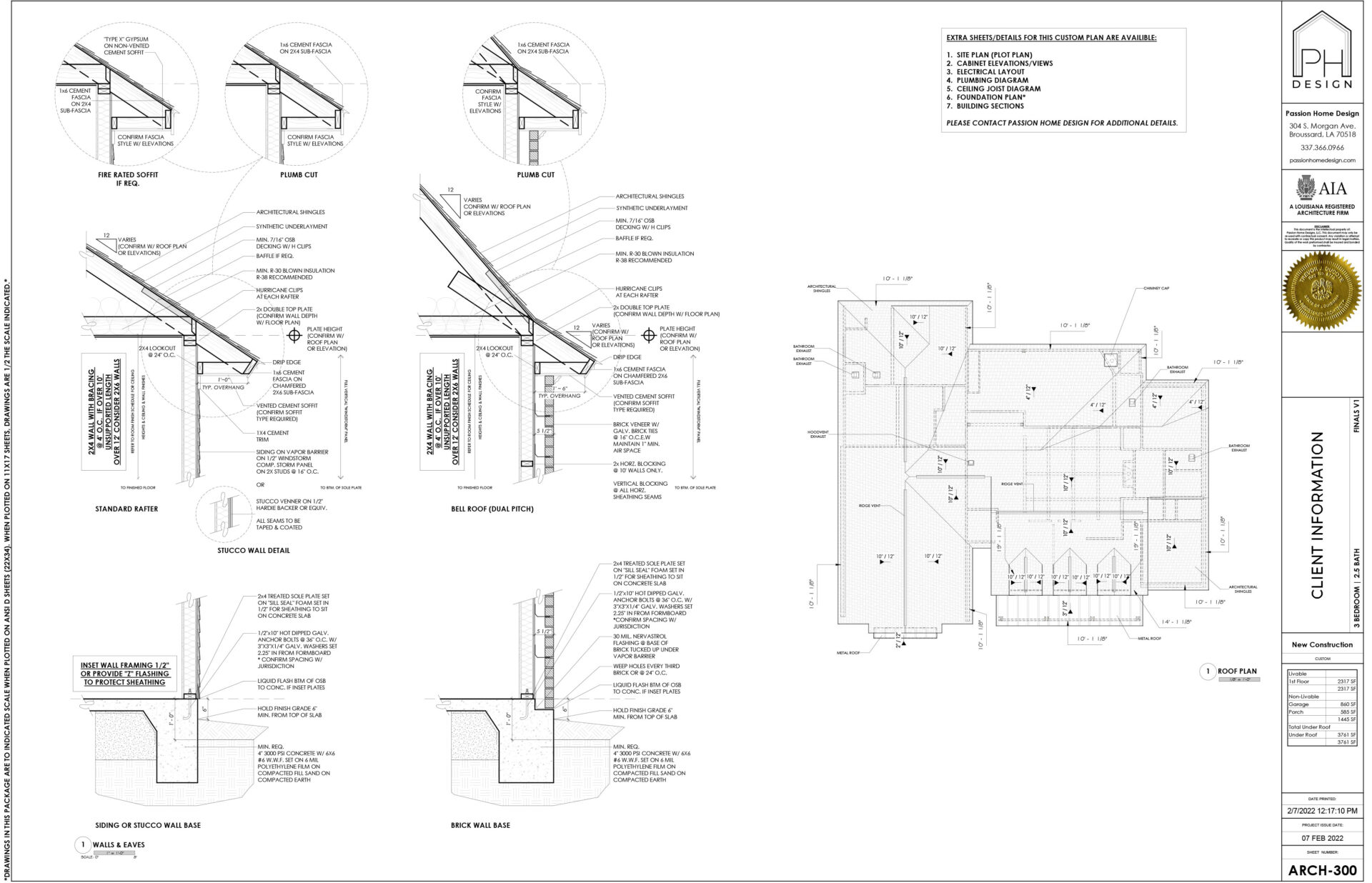
In buildings where certain interior or exterior walls vary in construction or material type, detailed drawings are provided and are illustrated in a separate sheet. Certain types of details such as advanced framing or zero energy details may result in additional fees.
The roof plan is a two-dimensional design that shows your roof from above. It contains annotations that provide information about the roof’s pitch, elevation, ridges, and slopes. It will call out exhaust and chimney locations as well as roof types. If this is an addition, it will specify which is existing and which is new construction.
ARCH-400 - Elevations & Building Sections
(Included in all Packages)


The elevation sheets are the 2D exterior faces of the building’s façade. It includes four faces namely, front, rear, left, and right-side elevation. The height of the building as well as the materials to be applied or conserved is indicated in the drawings with keynotes specifying significant external construction information.
If the house is a 2-story, it will include building sections if necessary. A section drawing displays a vertical slice transecting the building, usually along a principal axis. Sections are utilized to clarify the inner architecture of a part that cannot be properly depicted by concealed lines in exterior views.
DETAIL-500 Sheets

This closet detail sheet gives you and the builder a visual idea of what “1R1S” or “4S” mean. These drawings give everyone standards of how the closet/trim work is to be built and detailed out. Use these drawings to reference the floorplan for the “short terms” and see the full visual and dimensions of what we are specifying in the closets.

The Cabinet Elevations sheet includes the flat 2D view of the interior to show the built-in cabinets within the kitchen, utility, bathrooms, interior fireplace as well as any specialty detail.

When working on more complex projects, we will often include additional 3D views to clarify what is happening in specific locations of the project. They may include significant architectural features within the building such as stairways, flooring transitions, doors, windows, kitchen, closets, cabinetry, and other fixed elements in the interior. During the design process we offer all clients access to view the model in 3D to help resolve potential issues.
ARCH-600 - Electrical Layout
(Included in Architect and Complete Experience)

The electrical layout sheets are technical drawings that offer visual representations explaining electrical systems or circuits, sometimes known as wiring diagrams. This series of diagrams display the positions of all the power and data outlets, together with the lights and related switches. You will also see here the outline of the proper wiring and boxes required to manage all the lights and supply power to any additional devices.
Electrical layouts and the amount of electrical fixtures play a large role in the construction cost when acquiring bids from contractors. This sheet can help you understand one of the major costs in the home as well as accurately compare costs from multiple bids.
ARCH-650 – Mechanical Layout
(A La Carte Sheet)

Typically, the Mechanical plans are provided by an engineering firm. The mechanical plan details the layout and size of the ductwork, the position of the mechanical equipment, the location of the dampers, diffusers, thermostats, and, if necessary, supplemental cooling systems. This sheet can be added on by request, but not typically needed.
ARCH-700 - Plumbing & Foundation Dimensions
(Included in all Packages)

This sheet shows the dimensions of each plumbing location as well as the extents of the foundation. This is incredibly useful to the subcontractors to verify that the slab and plumbing are completed correctly. For stained concrete floors, this sheet is a must to help avoid plumbing pipes in the incorrect location.
ARCH-710 - Plumbing Diagram
(A La Carte Sheet)

The location and dimensions of the pipes used to provide clean water and remove waste will be shown on plumbing drawings. They will also demonstrate vent risers, which allow sewage air to exit the building securely and odorless.
ARCH-800 - Foundation Plan & Details
(A La Carte Sheet)

This sheet includes the footing details for the concrete foundation, the placements, and significant structural slab sections, and any significant connections. This drawing is one of the most important sheets and requires an architect or engineer’s stamp. We will provide a preliminary drawing for bidding purposes, and we hire a local engineer for stamped drawings. Most builders can work directly with the local sub labor to determine layout required by code.
ARCH-820 – Ceiling Joist Plan
(Included in Architect and Complete Experience)

This sheet provides the exact location of framing elements with the code compliance and span charts. Each one of these beams can be $500-1000+, and this sheet ensures that they are drawn in the accurate location as well as properly supporting the home’s structure.
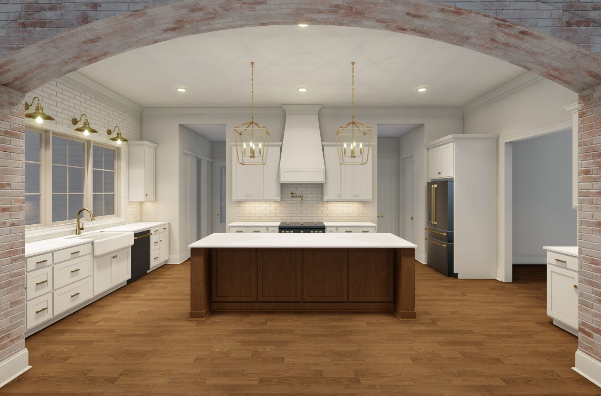
3D Renderings
(Included in Architect and Complete Experience)


(Only Included in Complete Experience or A La Carte)
To accurately grasp the architect’s meaning and properly interpret the building’s requirements, it is helpful for both clients and builders to be able to read and understand construction documentation. Drawings are crucial since they are utilized to communicate project technical data in a consistent way. We use keynotes to ensure every detail, such as closet/rods, microwave location, so on are included to help ease the relationships between the subcontractors in the field and the contractor/client.
Once we’ve completed the Preliminary Construction Documents to get the permit, we’ll have to wait for the competent authorities to process them. As the Preliminary Set is being processed, we complete the Final Construction set so that we can go straight to the contractor once the building permit is issued.
With our diverse background of experience and staff, we also offer a list of other “A La Carte” options for you to choose from. Make sure to check the proposal page for all kinds of other sheets we offer! We can be as full service as a client needs/requires.
If you’re new to reading construction plans, don’t worry. We as your designers will always be there to guide you and answer your questions every step of the way. Contact us today to get a quote for your next project.